Video latency tester
Description
In modern video streaming systems used in UAV and other applications which often require low latency, it is important to have a reliable way to measure the latency.
Usually people use so-called 'stopwatch method' which envolves running one on some screen (e.g. on laptop or phone)
with camera pointed on it, then taking a photo of both screens so you can compare both values and calculate the delay.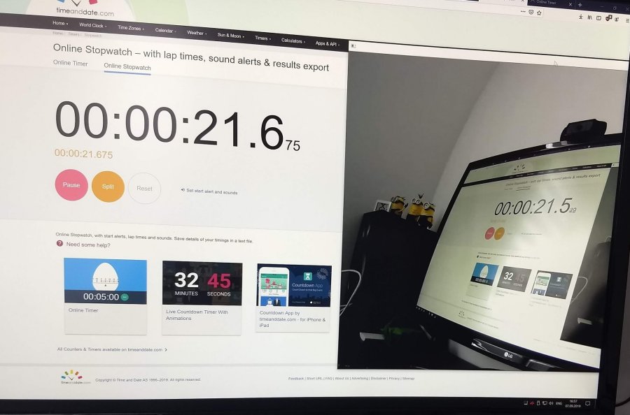
However such way has some disadvantages:
- You have to manually calculate each value
- It's sometimes hard to take a photo with clear time readings because of long exposure time which is usually applied in low light conditions, so you get values blurry
- It shows latency at exact monent of time, while it can differ because of camera frame rate
- You have to take a lot of photos in order to find min/max/avg latency
While working on SokilLink we realized that we need some faster and handier way to measure the latency, thus we decided to automate measurements. There were different setups but some of them used specific hardware, others didn't explain how to build them, so let's reinvent the wheel:
The tester turns LED on and off and reads values from sensor, then it compares it's readings in order to determine whether LED on display changed it's state and calculates time difference. Since cameras, displays and lighting conditions may differ between tests,
tester has to be properly calibrated before measurements.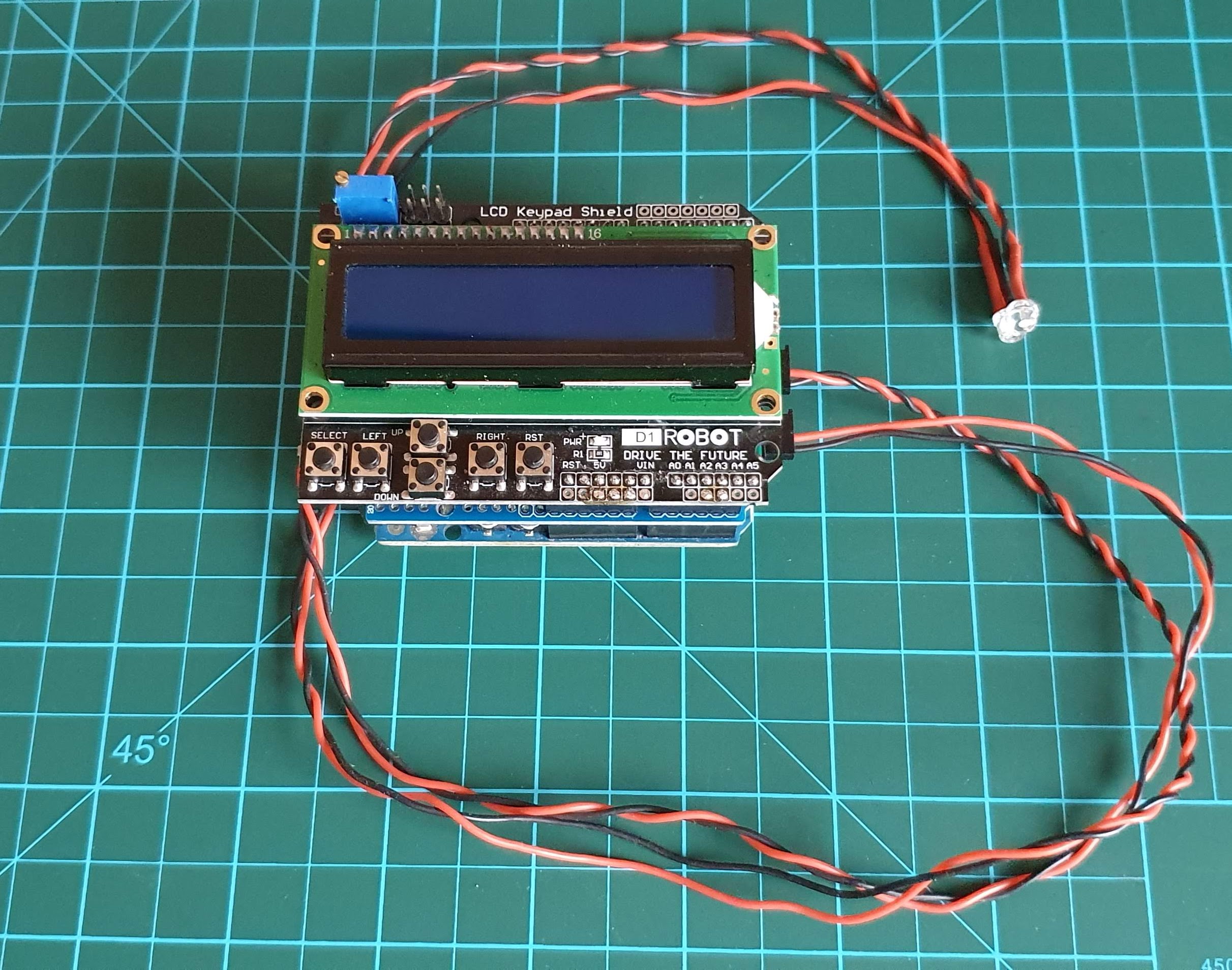
Hardware
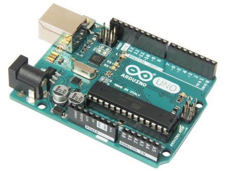
- Arduino Uno (or compatible one with shields support)
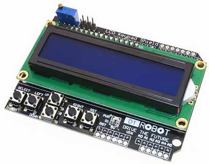
- 1602 LCD Keypad Shield For Arduino
- TEPT5700 light sensor
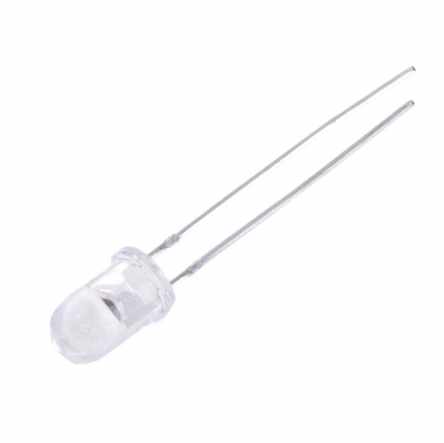
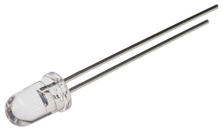
- Some bright 3.3V LED
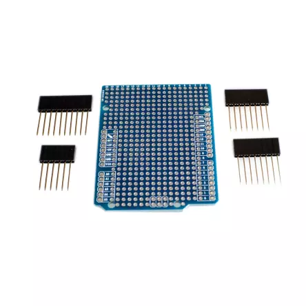
- [optional] Arduino breadboard shield (so you don't need to solder wires directly to Arduino or LCD shield)
- At least 1m of wires for convenient LED and sensor placement
- 100kOhm resistor
Connection diagram
Aside stacking shields on each other, you'll only need to connect:
- LED VCC > Arduino D11
- LED GND > Arduino GND
- TEPT5700 VCC > Arduino 5V
- TEPT5700 GND > Arduino A3
- Resistor > Arduino A3
- Resistor > Arduino GND
Software
Here is our simple Arduino sketch https://bitbucket.org/sokilaero/latencytest. Simply open it in Arduino IDE, compile and upload to your board. Feel free to send us fixes or improvements!
Working modes
Idle
In this mode tester displays current value read from the sensor (where 0 means no light and 5 - max light). While staying in this mode you can toggle LED state by pressing on "RIGHT" button. You can use it for proper LED and sensor alighnment, while LED is turned on readings should be at least 0.5 bigger than while it's turned off.
Calibration
You can start/stop calibration by pressing "LEFT" button. Tester will turn the LED on and off and measure sensor readings. You'll see "CAL" message if readings are different enough, otherwise "N/CAL" will be displayed.
Measurement
This mode measures the latency by turning the LED on and off and measuring time difference between it was actually turned on and picture changed on the display. You can start/stop measurement by pressing "SELECT" button.
Usage
After you powered on the tester, you need to ensure it is calibrated (calibrations are not stored between power cycles). Place LED in front of camera. Align the light sensor with part of the screen where you observe LED sensor. Then press "LEFT" button and wait for a second. "CAL" should be written on the screen in case of successful calibration, otherwise you need to repeat calibration in better conditions. Now you can press "SELECT" button which starts calibration. LED will start blinking rapidly. Wait few seconds until you see results on screen.